
After the HV test ends, the danger is still present
Author: Dr Stan Zurek
Primary topic: HV Insulation Testing Safety
Standards mentioned: IEEE 43-2013, IEEE 95-2002
Reading time: 12 min read
Every year, engineers and technicians are electrocuted — not during high-voltage insulation testing, but after it. The equipment looks safe. The voltage meter reads zero. But inside the insulation, lethal charge is still quietly stored and the dangerous voltage is rebuilding. This post explains why, and how a new technology from Megger called RE>Act™ is making HV DC insulation testing safer and faster.
INTRODUCTION
Picture this: a maintenance engineer has just finished a high-voltage DC insulation test on a large motor. The test instrument shows the voltage has discharged to zero, and the operator even used independently a HV discharge stick to ensure that the voltage is indeed discharged. A few minutes later his colleague reaches in to reconnect the motor terminal — and is hit by a shock of several hundred volts. The equipment “looked” safe. But inside the insulation, a hidden charge had been slowly rebuilding.
This phenomenon — known as absorption causing recovery voltage — is well documented in several IEEE and IEC standards, yet still misunderstood by the engineers working with HV equipment every day. RE>Act™, a new technology from Megger invented by the team: Paul Swinerd, Stan Zurek, Mark Tutton, Clive Taylor, and Mohineet Kaur, was created specifically to make this invisible hazard visible.
First: what is electrical insulation, really?
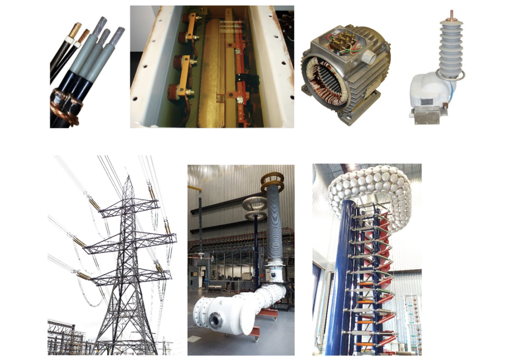
Every cable, motor or generator winding, transformer coil, bushing, insulator, surge arrester, and circuit breaker contains electrical insulation — the material that prevents current from flowing where it shouldn’t. Without insulation, high-voltage electricity cannot be safely contained or controlled.
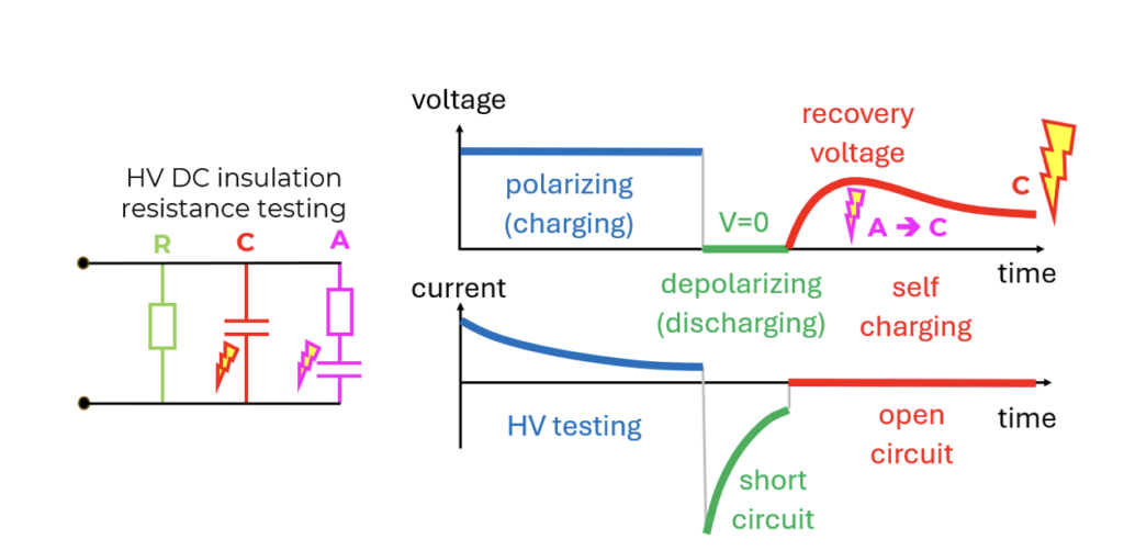
But insulation is not just a passive barrier. From an electrical engineering perspective, insulation behaves like a complex circuit made up of three components working simultaneously:
| Component | What it does |
|---|---|
| Resistance (R) | The classic insulation property — a high resistance means very little current leaks through. This is what insulation resistance (IR) tests measure in MΩ, GΩ, or TΩ. |
| Capacitance (C) | The insulation stores electrical charge, like a capacitor. This charge builds up quickly during a test and also discharges quickly. It is always dangerous when not discharged. |
| Absorption (A) | The most misunderstood component. Polarisation of molecules within the insulation material causes charge to be absorbed slowly — and released slowly. This is the hidden hazard. |
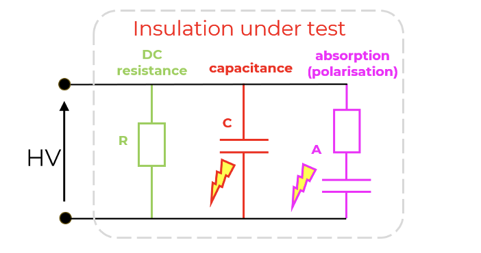
This three-part model — known as the “equivalent Debye model” — is the key to understanding why HV testing is dangerous even after the voltage source is switched off.
The hidden hazard: what happens after the test?
High voltage is applied to a piece of electrical equipment during the test. The capacitive component charges quickly and discharges quickly when the test ends — this is the part that most discharge procedures are designed to handle, and it is easy to understand.
But the absorption component is different. It charges slowly — and it discharges slowly. Worse still, even after the capacitive charge has been discharged to zero volts, the absorption charge begins to release itself — and this release creates a recovery voltage: the terminal voltage rises again, from zero, back up to potentially dangerous levels. All by itself.
Without any external source. So the capacitance becomes charged again, and charged capacitance is always dangerous.
⚠ THE DANGER NOBODY TALKS ABOUT
After an HV DC insulation test, the voltage at the equipment terminals may fall to zero — and then slowly rise again to hundreds and even thousands of volts due to absorption discharge. This is the leading cause of post-test electrocution. The equipment appears safe. It is not – if not handled properly.
The confusion is made worse by how standards describe this. IEEE 43-2013 defines the absorption current as one that decays “to nearly zero” — but “nearly zero” reading will be displayed differently by various equipment. Is 0.001 mA nearly zero?
To same people it may, but in reality it is certainly not. At high voltages, this small current can still transfer a lethal charge, from the absorption branch to the capacitive branch. The gap between laboratory theory and workshop reality has safety implications.
What do the standards actually say?
Both IEEE 43 and IEEE 95 — the two main standards governing HV DC insulation testing for rotating machines — acknowledge the hazard, but offer surprisingly vague guidance on how long to wait before touching the equipment.
“The danger exists for an indeterminate period of time. Dissipation of residual absorbed charge cannot be accelerated. The ground connection should be kept in place until the absorbed charge is completely dissipated. Typically, a minimum grounding time of at least 2 hours or 4 times the direct-voltage test duration, whichever is greater.” — IEEE 95-2002, Section 6.4
“The testing is not complete until the winding is discharged and there is no discernible voltage.” — IEEE 43-2013, Section 4
Read those carefully. The standards say: wait at least 2 hours. Or 4 times the test duration. And you can’t accelerate it. In practice, this means engineers face a choice: wait for hours (with no confirmation that it’s actually safe), or take a risk of confirming that the dangerous voltage is absent. But the standards don’t explain how to do that safely.
In busy maintenance environments, the pressure to get equipment back online is substantial. The lack of real-time feedback — any way to actually see whether the discharge is complete — is exactly the gap that RE>Act™ was designed to fill.
Introducing RE>Act™ — see the invisible
RE>Act™ stands for RE-Absorption Current Test. It’s a new inventive technology (patent applied for) integrated into the new Megger S1 and MIT 5–10–15 kV insulation testers.
The core idea is elegant: instead of disconnecting the equipment and hoping the discharge is complete, RE>Act™ connects a low-impedance ammeter through a discharge resistor while monitoring the actual discharge current in real time. Both the capacitive discharge and — crucially — the absorption discharge are measured and displayed as they happen.
The operator can now see the real discharge progress in real time, so the guessing is eliminated. So this “dual discharge” process can be now observed in real time by the operator.
What RE>Act™ actually measures
RE>Act™ monitors the discharge current through the insulation after an HV DC test, separating the capacitive current (discharging quickly to safe voltage) from the absorption current (slow, the source of recovery voltage, the hidden hazard).
When both components have fully dissipated — not just the capacitive one — the system confirms that the discharge is genuinely complete and safe.
How it works — step by step
01
Before the test: baseline measurement
RE>Act™ can be also run before the HV test to confirm the insulation is fully discharged. This establishes a baseline and gives the tester confidence about the starting condition.
02
HV DC test (e.g. Polarisation Index, 10 minutes)
The standard insulation resistance test such as PI is performed. During this phase, both capacitive and absorption charge accumulate in the insulation.
03
End of test: capacitive discharge
The insulation tester automatically connects discharge path to dissipate the capacitive voltage. The discharge is quick and the user can see the real voltage reducing quickly to zero (fast – seconds). Zero volts means that the capacitive component was discharged.
04
After the test: RE>Act™ discharge monitoring
RE>Act™ can monitor the slow discharge current due to absorption / polarisation. The operator sees the absorption decay of current (very slow — minutes to hours) as live, real-time information on the instrument display. Both numerical values and an animated range is clearly shown.
05
Safe to touch — visualised
When the absorption current has decayed to a truly negligible level — not just ‘nearly zero’ in the standard’s vague sense, but measurably zero — the system confirms the equipment is safe. No guesswork, no arbitrary waiting period.
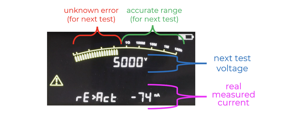
The RE>Act™ display shows additional information. At the bottom it is the real-time measured current during absorption discharge. In the middle it is the voltage of the next test as selected on the equipment. The actual voltage is zero (the insulation remain short-circuited), so the RE>Act™ test is inherently safe by itself. However, the information about the next test voltage and the real current is used for estimation of the usable measurement range for the next test on the same insulation.
If the next expected result is in the accurate range then the next test can be started even without waiting for the full discharge. But if the next result is likely to fall in the blocked range, then longer discharge is necessary, otherwise an unknown amount of measurement error will occur. This helps in avoiding condemning good insulation as bad, or worse still approving bad insulation as good.
Real-world results
RE>Act™ was tested on multiple types of equipment. Even on a relatively small 50 kVA oil-filled transformer, the discharge behaviour was clearly visualised and the absorption component took significantly longer to dissipate than the capacitive component. The absorption current was above 1 nA even 20 min after the test was finished. On a 90-metre long HV cable (20 kV rated, 16 nF capacitance), the cable remained unsafe for over 25 min after the capacitive voltage had reached zero — precisely as IEEE 95 warns, but now visible and quantifiable in real time.
Operators who used RE>Act™ on HV motors were able to significantly improve productivity, because they could significantly reduce the 2 h blind waiting time. But more importantly – they were able to eliminate the invisible danger.
PI Predictor™ — faster testing without compromising safety
RE>Act™ solves the safety side of the equation. But the productivity is also improved, almost as an effortless byproduct of using this feature.
The Polarisation Index (PI) is a standard diagnostic test that compares the insulation resistance at 10 min and 1 min. A healthy insulation shows increasing resistance over time (good absorption behaviour). But waiting 10 min for every test — and then waiting another 40 min (or even 2 h, depending on the standard) for safe discharge — creates a significant bottleneck in maintenance schedules.
PI Predictor™ exploits a physical symmetry: shorter polarisation (absorption) means shorter depolarisation (reabsorption). By running a shorter polarisation test and measuring the depolarisation behaviour, the PI Predictor™ algorithm can predict the 10-minute PI result in typically in just half of the time.
| 50 min Standard PI test + discharge (10 min charge + 40 min discharge) | 14 min With PI Predictor™ + RE>Act™ (5 min charge + 9 min discharge) | 72% Reduction in total test time — while remaining equally safe and accurate |
The test was validated on a 90 kW LV motor. The predicted PI result matched the standard 10-minute result. Total test time: 14 min vs. 50 min. For facilities running dozens of insulation tests per year — on motors, cables, transformers, generators — the productivity gains compound rapidly.
Three benefits that change how HV testing works
| Benefit | What it means in practice |
|---|---|
| Safety | Visualise the complete discharge process — both capacitive and absorption — in real time. Know with certainty when it is safe to touch the equipment, rather than guessing based on a 2-hour waiting rule. |
| Accuracy | Quantify the correct measurement range before the next test. RE>Act™ shows not just whether discharge is complete, but the prospective IR range for the next test cycle on the same insulation — eliminating errors due to negative currents. |
| Productivity | Eliminate unnecessary “blind” discharge time. With PI Predictor™, as the total test + discharge time can be reduced by up to 72% while maintaining the same safety margin and diagnostic accuracy. |
Why this matters beyond the test lab
HV insulation testing is performed routinely on industrial motors, generators, transformers, and cables — in power stations, manufacturing plants, marine vessels, wind farms, and anywhere else large rotating machines or power distribution equipment is maintained.
The engineers doing this work might be experienced professionals. But experience doesn’t protect you from a hazard you can’t see, and boring routine can be dangerous. Recovery voltage — the insulation recharging itself — is invisible, silent, and can appear minutes or hours after the test ends. The fact that IEEE standards call for 2-hour waiting periods tells you everything about the severity of the risk. And that is with insulation short-circuited. Without short-circuiting the danger can remain for “indefinite” time.
RE>Act™ doesn’t change the physics. It makes the physics visible. And in safety-critical work, the difference between “I think it’s discharged” and “the instrument confirms it’s discharged” is the difference between risk and certainty.
“Safety — visualise the complete discharge process in real time. Accuracy — quantify the correct measurement range before the next test. Productivity — eliminate unnecessary blind discharge time.”
— Dr Stan Zurek — RE>Act™ summary
Key Takeaways
✅ Electrical insulation stores charge in two ways: capacitive (fast) and absorption (slow).
✅ After an HV DC test, recovery voltage can rebuild to dangerous levels — even after the meter reads 0 V.
✅ IEEE standards recommend 2-hour waiting periods, with no way to confirm when it’s truly safe.
✅ RE>Act™ makes the full discharge process visible in real time — confirming safety, not assuming it.
✅ PI Predictor™ significantly reduces total test + discharge time, with no loss of accuracy or safety.
✅ Available in Megger S1 and MIT series testers (5 kV, 10 kV, 15 kV).

Would you like to know more?

Marcin Ruta
Electrical Safety Consultant
MR Power Systems