How Do You Protect a Power Line When It Gets More Complicated?
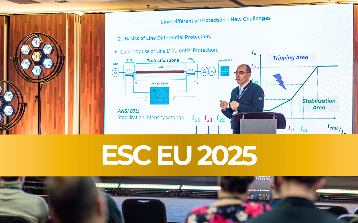
Based on a presentation by Dr. Ricardo Granizo Arrabé, Stucke Elektronik GmbH | ESC EU 2025 Conference
Author: Dr. Ricardo Granizo Arrabe
Primary topic: Line Differential Protection (ANSI 87L)
Standards mentioned: ANSI 87L
Reading time: 8 min read
The Big Picture: Why This Matters
Europe’s electricity grid is under serious strain. Almost every major substation is running at or near its maximum capacity. On top of that, we’re connecting more and more renewable energy sources — solar farms, wind parks — which need new power lines and transformers to bring their electricity into the grid.
To keep up, engineers are adding new lines and transformers to existing infrastructure. But this creates a problem: the safety systems that protect those lines were designed for simpler setups. Now, the setups are getting more complex.
This article explains one key safety system — called Line Differential Protection (or ANSI 87L) — and how it’s being adapted to work in these newer, more complicated configurations.
1. What Is Line Differential Protection?
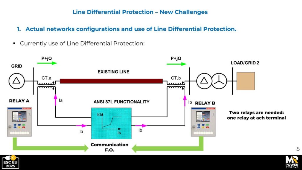
Think of a power line like a water pipe. If you measure the water going in at one end and the water coming out at the other, they should be equal. If they’re not — some water is leaking somewhere.
Line Differential Protection works the same way with electricity. Sensors called Current Transformers (CTs) measure the current (electricity flow) at both ends of a protected section of line. Under normal conditions, what goes in equals what comes out. If there’s a difference — a fault (like a short circuit or a break in the insulation) — the system detects it and automatically switches off that section to prevent damage or danger.
Why is this important?
A fault on a high-voltage power line can be extremely dangerous — causing fires, equipment damage, or widespread outages. The protection system must detect faults in milliseconds and switch off the affected section before serious damage occurs.
Standard Line Differential Protection uses two measurement points (one at each end of the line) and works very well for simple, straight lines. The challenge is: what happens when the line isn’t simple anymore?
2. Three New Challenges
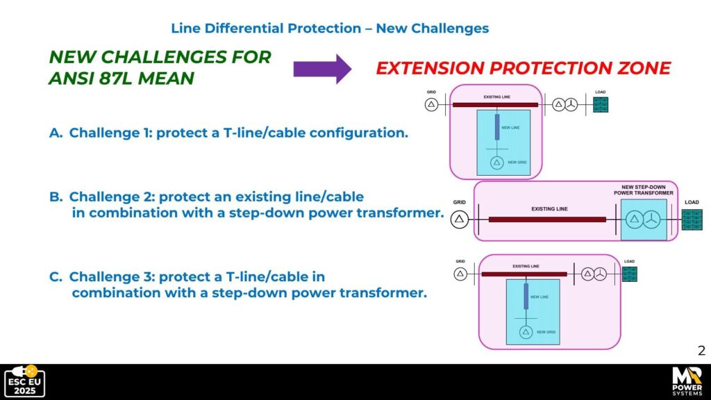
Modern grid development is creating three types of configurations that go beyond the classic straight-line setup:
| Challenge | What it is | Main problem |
|---|---|---|
| A | A line that splits into a T-shape (three branches) | Three ends to measure, not two |
| B | A line with a transformer attached at the end | The transformer shifts the signal in ways the sensor must account for |
| C | A T-shaped line with a transformer in the mix | Both A and B combined — needs four sensors and more complex calculations |
3. Challenge A: The T-Shaped Line
What’s the problem?
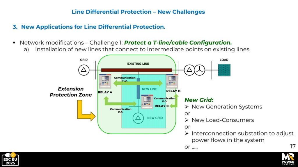
Imagine a road that splits into three directions. At each road end, you have a sensor. Now, instead of just checking that traffic in equals traffic out at two points, you need to balance three roads at once. That’s what happens with a T-junction in a power line.
With three branches, you need three protection relays (safety devices), all connected to each other by a fiber-optic cable so they can share their measurements in real time.
The hidden complication: cable shields
Modern underground cables are wrapped in a metal shield — a bit like the outer foil on a coaxial TV cable. This shield helps contain the electric field and carries fault current if something goes wrong. The tricky part is how the shield is connected to the ground.
There are three common ways to do this: Solid Bonding (both ends grounded), Mid-Point Connection (only the middle is grounded), and Cross Bonding (the most common in long high-voltage cables, where sections of shield are swapped and grounded in a pattern that nearly cancels out induced currents).
The protection system sees these shield currents too. It needs to know which currents are normal and which signal a real fault. The algorithm has to be configured for the grounding method used in each installation.
4. Challenge B: The Line with a Transformer
Why are transformers being added to existing lines?
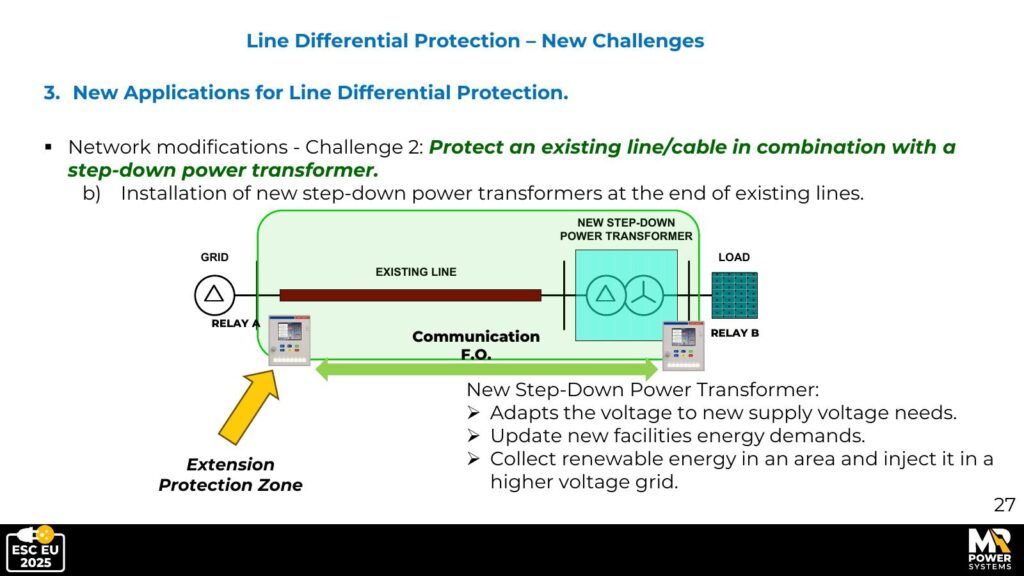
A transformer changes the voltage level of electricity — for example, from 30,000 volts (30 kV) down to 20,000 volts (20 kV) — so it can be distributed to homes and businesses. As new areas or renewable energy installations are connected, engineers often attach a new transformer at the end of an existing cable rather than building a completely new substation.
Two things that make this tricky
1. Phase shift: Transformers don’t just change voltage — they also shift the timing of the electrical wave. The protection relay on one side sees the current slightly out of step with the relay on the other side. Without correction, this looks like a constant fault. The relay must be programmed to apply the right correction factor.
2. The tap changer: Most transformers can fine-tune their output voltage using an automatic mechanism called an On-Load Tap Changer (OLTC). Each step changes the current ratio by about 1–2%. The protection settings must cover the full range of tap positions while still being sensitive enough to catch real faults.
Where to put the sensors?
In this setup, the current sensors must be placed at the entry point of the cable (high-voltage side) AND at the output of the transformer (low-voltage side). This ensures the whole cable-plus-transformer zone is covered. Any fault anywhere in between will be detected.
5. Challenge C: T-Junction + Transformer
This is the most complex case — a T-shaped line where one branch connects to a transformer. You now need four protection relays, all communicating with each other.
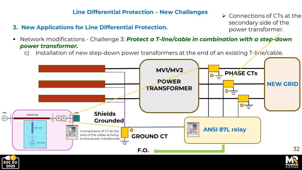
The system must handle everything from Challenges A and B at the same time:
- Balancing currents across three cable branches
- Correcting for the transformer’s phase shift
- Staying stable across all tap changer positions
- Correctly interpreting cable shield currents
It’s a lot — but modern protection hardware and software can handle it, provided it’s set up correctly.
6. Does It Actually Work? Simulation Results
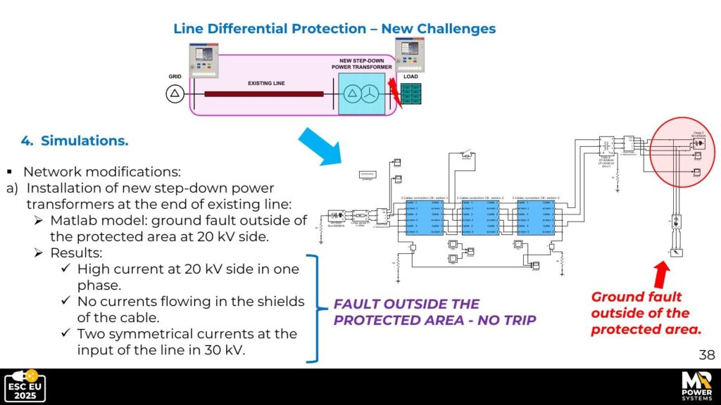
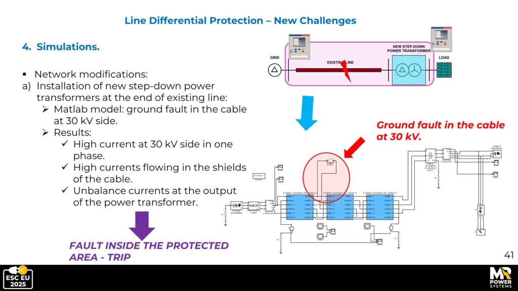
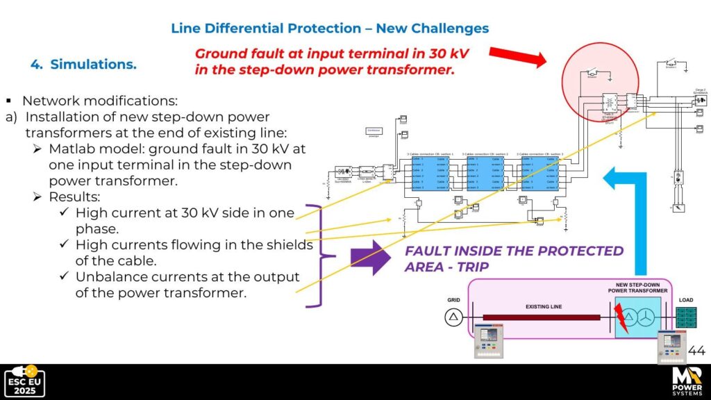
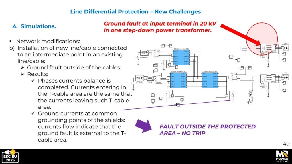
Before deploying these systems on a real power grid, engineers test them in computer simulations (MATLAB/Simulink). The key test for each scenario: does the protection correctly trip (switch off) when there’s a fault inside the protected zone, and correctly stay on when the fault is outside?
Challenge B: Fault outside the protected zone
Challenge B: Fault inside the cable
Challenge B: Fault at transformer input terminals
Challenge A: Fault outside the T-cable area
Challenge A: Fault inside the T-cable area
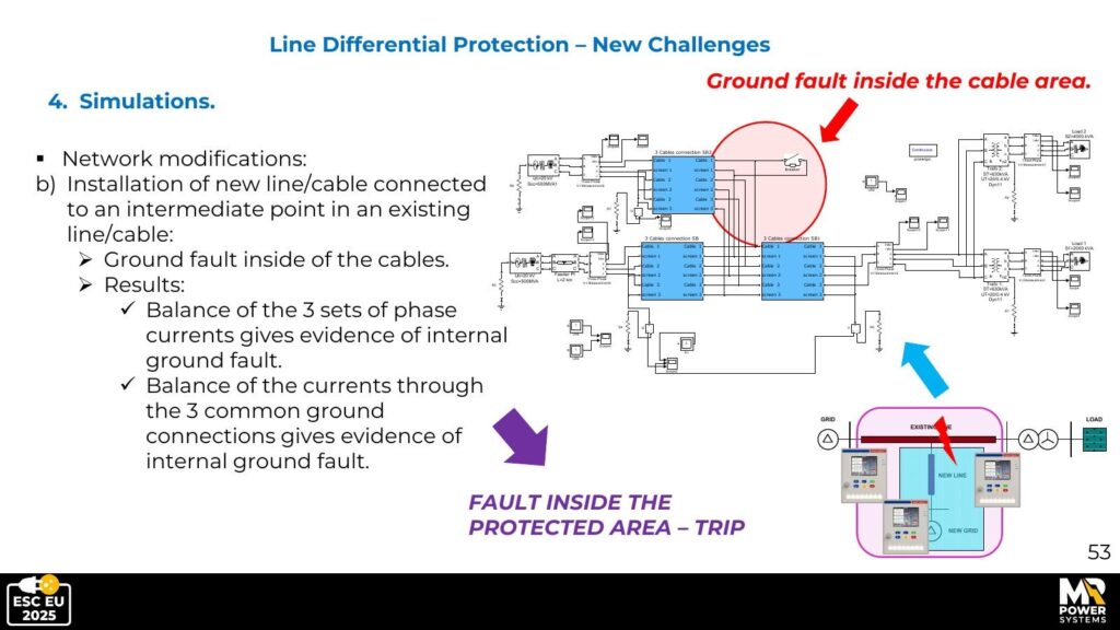
Challenge C: Summary result
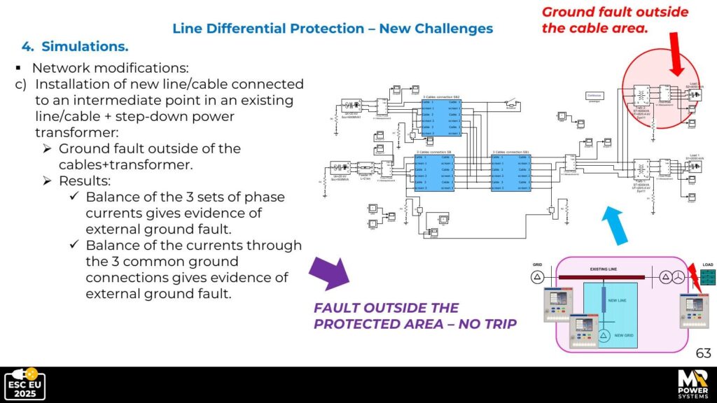
In every case, the extended ANSI 87L algorithm correctly identified whether the fault was inside or outside the protection zone. No false alarms, no missed faults.
7. Key Lessons
The basic principle still works — but needs adaptation
The ‘what goes in must equal what comes out’ principle is still valid for all three configurations. What changes is the implementation: more sensors, more communication between devices, and more sophisticated calculations.
Sensor placement is critical
You can’t just put the current sensors anywhere convenient. The rule is straightforward: sensors must be placed at every point where current can enter or leave the protected zone. Getting this wrong doesn’t just reduce effectiveness — it can make the protection completely blind to certain types of faults.
Cable shield currents are useful, not a nuisance
Engineers sometimes see shield currents as an unwanted complication. In reality, they’re a valuable signal. During an internal cable fault, shield currents spike to levels that are easy to distinguish from normal operation. A well-designed system uses this as an extra early-warning indicator.
The tap changer must be factored in from the start
If a transformer with an automatic tap changer is included in the protected zone, the protection settings must cover the full range of tap positions. A setting that works fine at mid-range may cause false trips at the extremes. The safest approach is to verify this through simulation before the system goes live.
8. Conclusion
Line Differential Protection is one of the most reliable safety tools in the power engineer’s toolkit — it’s fast, accurate, and robust. These qualities don’t disappear as power grids become more complex, but they do require more careful engineering to preserve.
The three challenges described in this article reflect real trends: more underground cable, more renewable energy connections, and more complex layouts driven by the need to expand grids without always building entirely new infrastructure.
The good news is that all three configurations can be safely and reliably protected with modern systems — as long as engineers follow these principles:
- Define the protection zone clearly and put sensors at every boundary point.
- Account for the cable shield grounding method in the protection algorithm.
- Apply the correct correction for the transformer’s phase shift.
- Design the settings to remain stable across the full tap changer range.
- Use simulation to verify everything before commissioning.
Would you like to know more?

Marcin Ruta
Electrical Safety Consultant
MR Power Systems