Arc Flash Risk Assessment – Complete Step-by-StepGuide
By Hency Roballo, MR Power Systems
Author: Hency Roballo
Primary topic: Arc Flash Risk Assessment
Standards mentioned: NFPA 70E, IEEE 1584, IEEE 1584.1, CSA Z462, OSHA 1910.269, DGUV 203-077, IEC 60909, IEC 61363
Reading time: 9 min read
What Is Arc Flash and Why Is It Dangerous?
Let’s be honest: the risk of arc flash is still widely underestimated or misunderstood. When people hear the term electrical hazard, they often think only of electric shock. While electric shock
is undeniably dangerous, arc flash represents a completely different—
and often more devastating—threat. Unlike shock hazards, an arc flash
can release an enormous amount of energy in a split second, exposing
workers to extreme heat, explosive pressure, and molten metal. For anyone
working in the electrical industry, electrical maintenance, electrical
safety, or related fields, misunderstanding or overlooking the danger
of arc flash can have severe or even fatal consequences.
Electrical hazards are present in our daily lives, so it’s crucial to
be aware of them and take the necessary precautions to ensure we get
home safely from work.
The aim of this article is to explain how arc flash risk assessment
process looks like, from the initial contact to installing label on the
electrical panel door. But before we get into the process, let’s make
sure everyone understands what it’s all about.
Electrical Hazards vs Electrical Risk – Key Differences
These terms may sound similar, but for those who regularly work in the
electrical sector, it’s essential to know the definition. An electrical hazard is the source of the potential to cause harm, for example, damaged equipment that could cause a short circuit or an arc flash. On the other hand, an electrical risk is the likelihood and severity of
harm when a person is exposed to an electrical hazard.
Types of Electrical Hazards in the Workplace
When it comes to electrical hazards, the list is longer than we think.
Below are some examples of electrical hazards:
- Electric shock
- Arc flash hazard
- Arc blast
- Electrostatic discharge
- Electrical fires
- Electromagnetic field exposure
- Explosions in Ex areas
- Burns from hot surfaces of energized components
- Induced voltage
- Battery fires and explosions
Arc Flash: Real Risks, Real Costs
Most of the safety training focuses on shock hazards. Arc flash often gets only a slide,
maybe a warning label without important information, sometimes just a sticker for electric shock, and then everyone moves on. That’s a problem—because in terms of raw destructive potential, arc flash is in a completely different category.
Here are some numbers that tend to attract people’s attention:
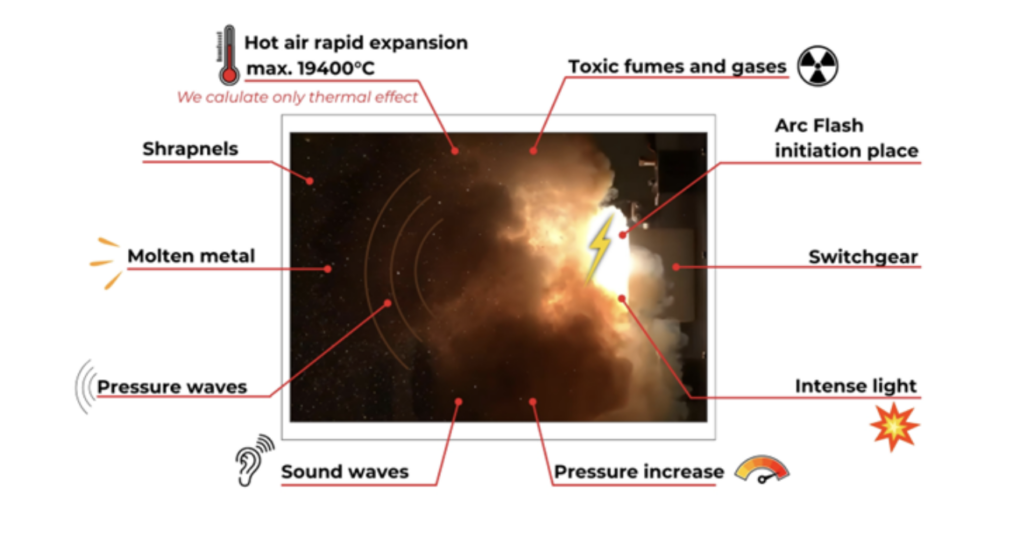
An arc flash is not just an electrical fault but a violent arc flash phenomenon—a rapid, uncontrolled release of energy that resembles an explosion more than a typical electrical hazard. In milliseconds, temperatures above 19,000 °C, roughly 15 times hotter than volcanic
magma, can vaporize copper and force it to expand tens of thousands of times its original volume.
This sudden expansion generates powerful pressure waves capable of knocking workers to the ground and hurling molten metal at extreme speeds, while intense thermal radiation causes severe burns without direct contact. Blinding light, deafening noise,
and clouds of superheated gases and metal vapors further compound the danger. Unlike electric shock, proximity alone is enough to underestimate this phenomenon means overlooking one of the most destructive hazards in electrical work.
And the costs aren’t just human. A few real-world examples
- OVH SBG1 — arcing fault in a UPS battery room: €105 million loss
- Ocado warehouse, Andover UK — battery charger fault: £110 million damage + £132k fire-fighting costs
- Notre-Dame Cathedral — officially attributed to an electrical fault: €552 million reconstruction cost
The point isn’t to terrify anyone. It’s to establish that this is worth
doing properly.
Hierarchy of Controls in Electrical Safety
Hierarchy of Controls is a safety framework used to reduce or eliminate exposure to hazards in the workplace. It ranks control measures from the most effective to the least effective, helping organizations prioritize solutions that provide the highest level of protection.
Working from most effective to least effective
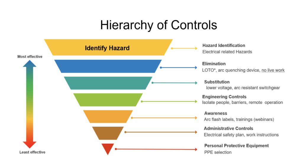
- Identification: We could say that the first step is to identify the risks in the workplace. Once electrical hazards are recognized, the next step is to reduce or eliminate them through engineering controls. However, personal protective equipment is still mandatory. The question is how to correctly understand and apply this process in the workplace.
- Elimination: No live work. LOTO. Arc quenching devices. If you can de-energize it, de-energize it. This is always the preferred option.
- Substitution: Lower operating voltage. Arc-resistant switchgear. If you can change the system to reduce the inherent hazard, do it at design stage.
- Engineering Controls: Physical barriers. Remote operation. Isolating people from the hazard spatially. Things that don’t depend on human behavior to work.
- Awareness: Arc flash labels. Training. People need to know the hazard exists and understand what the labels mean. This is necessary but not sufficient on its own.
- Administrative Controls: Electrical safety plans. Work instructions. Written procedures for how tasks get done safely.
- PPE: The correct arc-rated clothing and equipment for the calculated incident energy. Essential, but it only protects the person already exposed to the hazard.
A good arc flash study informs all of these levels, not just the PPE selection.
In conclusion, when an employer implements all elements of the Hierarchy of Controls, the level of risk can be significantly reduced or even eliminated. As a result, the tasks performed by employees transition from relying on the least effective protective measures to the most effective and safest controls, leading to a substantially safer work environment.
How is it understood in the workplace?
In practice, many workplaces are familiar with PPE and administrative controls because they are easier to implement. However, higher-level controls such as elimination, substitution, and engineering controls are often underestimated or overlooked due to cost, design constraints, or lack of early planning.
Do people know about it?
While the Hierarchy of Controls is widely recognized in safety standards and professional guidance, not everyone truly understands or applies it correctly. In many cases, it is treated as a theoretical concept rather than a practical decision-making tool. Improving awareness and
application of the hierarchy is essential for managing high-energy hazards such as arc flash effectively.
Key Arc Flash Standards (NFPA 70E, IEEE 1584, OSHA)
Regarding arc flash performance, it is necessary to be familiar with and apply the relevant standards; the most important ones are listed below:
| Standard | Description |
|---|---|
| NFPA 70E (2024) | Standard for Electrical Safety in the Workplace |
| IEEE 1584-2018 | Guide for Performing Arc-Flash Hazard Calculations |
| IEEE 1584.1-2013 | Guide for the Specification of Arc-Flash Hazard Calculations |
| CSA Z462-2024 | Workplace Electrical Safety |
| EPRI TR-2011 | Arc Flash Hazard Analysis Methodology |
| OSHA 1910.269 Appendix E | Protection From Flames and Electric Arcs |
| DGUV 203-077 | Selection of Personal Protective Equipment for Electrical Arc Hazards |
Supporting standards for the short-circuit side: IEC 60909 (general), IEC 61363 (marine and offshore). ANSI, IEEE, EN, BS standards as appropriate to the system being studied.
It is important to clarify that each country has its own standards. In general, some approach limits and protection zone requirements may change according to national regulations; however, the calculation methodology is usually the same as, or based on, IEEE 1584-2018.
Step-by-Step Arc Flash Risk Assessment Process
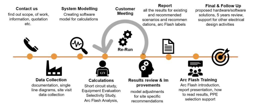
Here is how a proper arc flash risk assessment gets done.
Step 1: Customer meeting:
Before initiating any analysis or field visit, it is essential to clearly define and fully understand the project scope. This requires close collaboration with the client to determine the project size, identify the applicable standards, and collect all critical information necessary
to prepare an accurate and effective offer.
Step 2: Data Collection:
Before conducting an on‑site visit for data collection, all available technical information should be reviewed, and the data‑collection format prepared. During the field visit, relevant data is collected accurately, and a safety inspection is carried out. The findings are then documented in a site report that includes observations, analysis, and safety recommendations aimed at improving workplace safety.
Step 3: System Modelling:
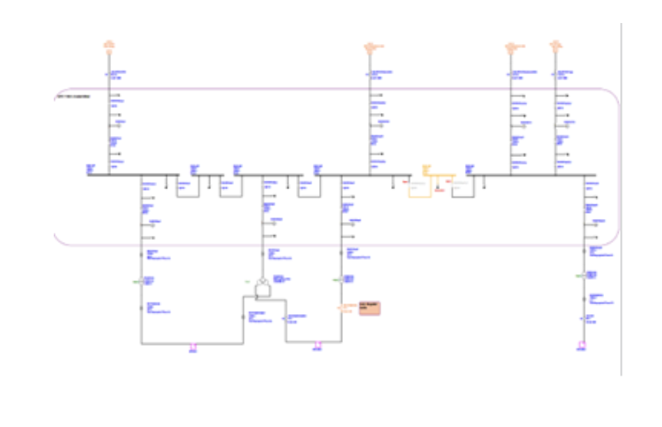
Develop a digital twin of the electrical network using specialized software that accurately reflects the actual installed system. The electrical model shall be created with comprehensive and precise details to ensure it faithfully represents the real-world configuration, equipment
characteristics, and operating conditions.
Step 4: Electrical Analysis Calculations.
Performance an Electrical Analysis calculations based in all standards:
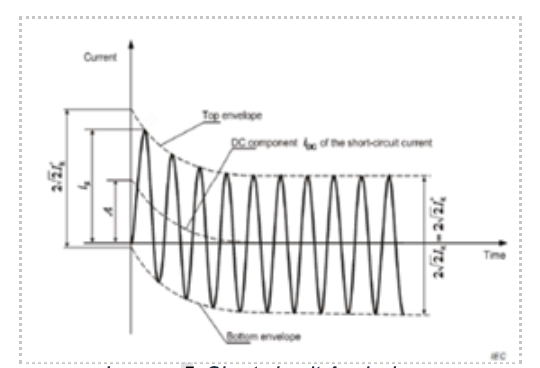
- Short Circuit Analysis. IEC 60909 /ANSI
- Short Circuit Equipment Evaluation
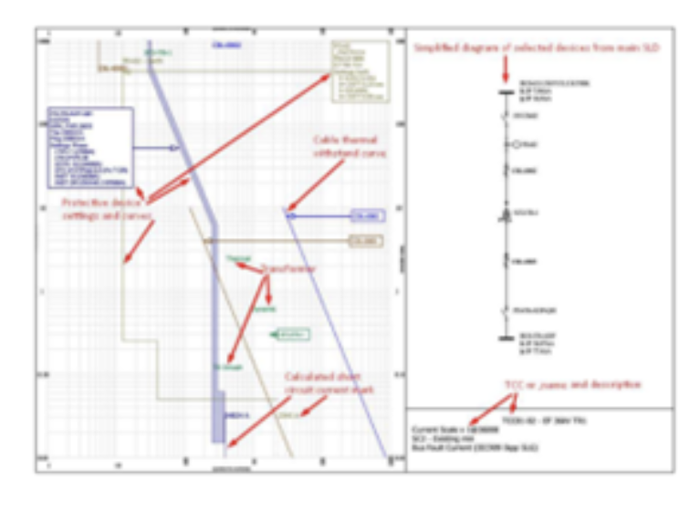
- Selectivity Analysis to find protection issues for exiting situation and provide recommendations for improvements for future adjustments
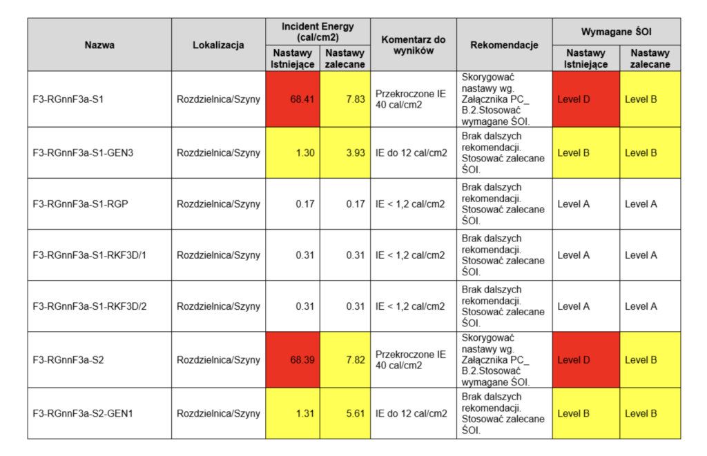
- Arc Flash Analysis – for existing situation acc. IEEE1584 -2018 / sometimes DGUV203-077, provide recommendations for improvements for future adjustments.
Step 5: Report:
The final report includes all results, analysis tables for existing and recommended situations, different scenarios configuration, recommendations, modeling data, single‑line diagrams, and equipment labeling information, compiled and delivered in appropriate formats such as Word, PDF, and Excel.
Step 6: Customer Meeting:
It is essential to hold a meeting with the client to review the report results, discuss identified issues within the electrical installation, and present the proposed recommendations developed in accordance with the Hierarchy of Controls.
Step 7: Training:
Provide technical training on arc-flash hazards, preferably conducted on-site, with online delivery as an alternative. The training covers hazard identification, arc-flash warning labels, proper selection and use of personal protective equipment (PPE), and methods to reduce or eliminate risks through engineering controls, in accordance with the report findings.
Step 8: Final & follow up:
Overall, periodic revisions should be carried out, with results updated at least every five years or following any significant modifications to the electrical system. This process may include retraining workers and updating or replacing equipment warning labels as necessary.
Would you like to know more?

Marcin Ruta
Electrical Safety Consultant
MR Power Systems