Battery Energy Storage System Safety: Safe Operation and Electrical Hazards
Safe Operation of Battery Energy Storage Systems: Electrical Hazards and Risk Management
Understanding the hazards involved in operating these systems is essential for keeping both personnel and the electrical installations safe. Energy storage is now a cornerstone of the energy transition and trying to keep power systems stable. But as these installations grow in scale and become more deeply integrated into the grid, the conventional approach to electrical safety simply isn’t enough anymore.
In a BESS, several things are happening at the same time:
- both DC and AC voltages are present
- short-circuit currents can be dozens of kilo amps
- there’s a chemical energy source on board (Li-Ion, LiFePO₄, NMC)
That combination forces us to look at the hazards holistically. Unlike conventional electrical installations, a BESS involves coupled electrical, thermal, and chemical phenomena and that significantly increases the complexity of any risk analysis.
Battery Energy Storage System Safety: Key Electrical Hazards
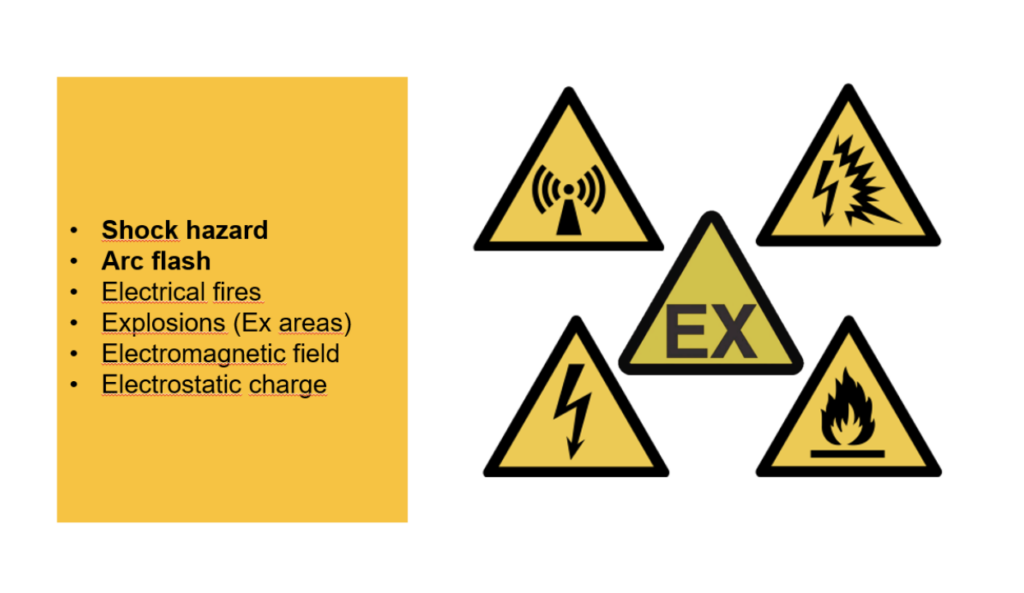
Operating an energy storage system brings with it several major hazard categories, and they all interact with one another. The most important are:
- electric shock (both AC and DC)
- arc flash burns (both AC and DC)
- fire and thermal runaway
- external short circuits
- chemical hazards (liquids and gases)
A Closer Look at Each Hazard
DC Electric Shock
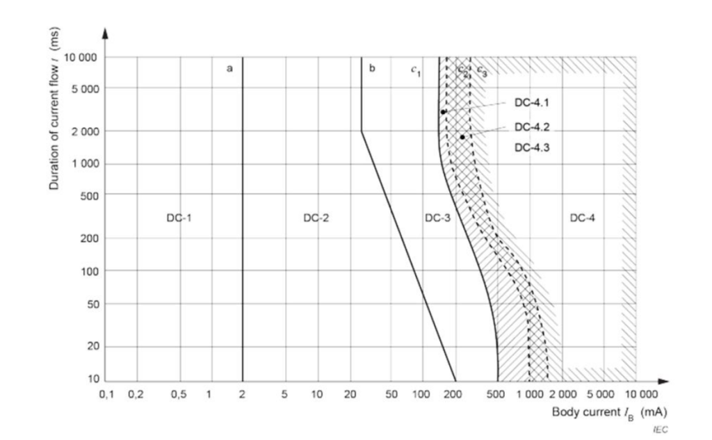
DC electric shock is a particularly serious concern in energy storage systems, mainly because voltage levels keep climbing — often above 800 VDC. Unlike alternating current, direct current has no natural zero crossing, which means muscle contraction is continuous rather than intermitten. The longer current keeps flowing through the body, the greater the risk of serious tissue damage, cardiac disturbance, and deep internal burns. On top of that, AC voltage is present in a BESS as well.
Shock can occur during:
- routine operational work
- damage to battery modules (where the voltage exceeds 120 VDC)
- insulation failure
It’s also worth remembering that, under EN50110, isolating the work area doesn’t fully apply when you’re working near batteries. We can’t completely “switch off” or discharge a battery’s energy. In practice, the protections we rely on are:
- defined procedures for working around batteries
- personal protective equipment
- engineering solutions (battery sectioning, modular design, module-level protection, and so on)
Arc Flash in BESS
An arcing fault is a real hazard during BESS operation. DC voltages here exceed 120 VDC and, as of today, reach up to 1500 VDC (the low-voltage limit for DC under EN 50110). In DC installations, the energy released by an arc depends very heavily on the short-circuit current and on the source’s ability to sustain the arc. Arcing faults can be triggered by:
- insulation damage
- operational work (human error)
- installation errors
- environmental factors (moisture, contamination, flooding)
- internal and external short circuits
Unlike a bolted (metallic) fault, an arcing fault carries a certain arc impedance, and that has real consequences:
- arc-fault currents are harder to detect because they are lower
- they’re harder to interrupt unless you use solid state circuit breakers
- detection and clearing can take longer time
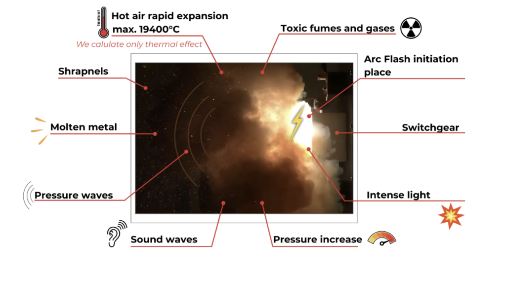
The distinctive features of an electric arc include:
- temperatures reaching up to 19,400 °C
- light radiation (UVA/UVB)
- a pressure rise (shock wave for now is not DC issue, for now)
- ionization and heating of the surrounding air
- ejection of molten metal
- shrapnel travelling at speeds up to 1,100 km/h
- a sound wave reaching as much as 160 dB
Thermal Runaway
Thermal runaway is one of the most serious hazards in any energy storage system. It happens when a cell loses control of its own thermal balance — most often triggered by mechanical damage, electrical overload, high temperature, or internal defects. The graphic below lays out the causes, the mechanism, and the consequences in a very straightforward way.
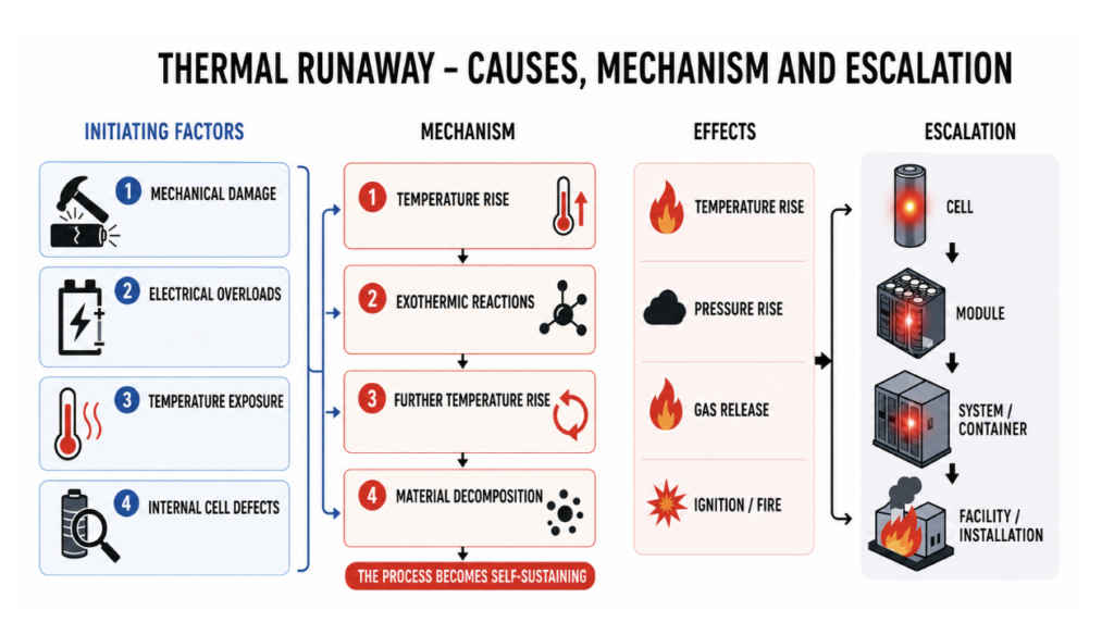
The nature of the hazard depends on the cell technology and chemistry. The most vulnerable cells are made with:
- Lithium Cobalt Oxide (LCO)
- Nickel Manganese Cobalt (NMC)
The least vulnerable are:
- Lithium Iron Phosphate (LFP)
- Solid-State Batteries (solid electrolyte)
In battery energy storage systems, a particular concern is the presence of oxidizing substances. Under fault conditions (thermal runaway,for instance), these can significantly intensify a fire and allow it to keep developing independently of any oxygen from the surrounding air. Under the requirements of NFPA 400 and NFPA 704, systems containing such materials should be properly classified and labelled,and their operation should account for scenarios involving the release of oxidizing substances.
Thermal runaway is set off by:
- Mechanical damage — puncture, crushing, internal short circuit
- Electrical overload — overcharging, over-discharging, excessive current
- Thermal effects — high ambient temperature, fire, loss of cooling
- Internal cell defects — manufacturing flaws that lead to a short circuit over time
Short Circuits in DC Circuits
Short circuits in energy storage systems are a special case because of the battery cells’ very high short circuit current capability. The focus here is on battery energy storage used in industrial and grid-scale installations. To give a sense of scale: utility-scale storage is built from 20-foot BESS containers, typically rated up to 5 MWh / 1300 VDC eg. (12×1P416S) — meaning 12 clusters of 416 modules at 3.2 V each.
Systems built from these containers reach truly large figures:
- Edwards & Sanborn Solar — USA, California: 821 MW / 3,287 MWh
- Collie Battery — Australia: 560 MW / 2,240 MWh
- Bisha BESS — Saudi Arabia: 500 MW / 2,000 MWh
In large storage systems, short circuits matter not only locally but at the system level too. These systems also serve a range of roles, from storing energy locally to providing fast frequency support. From the storage system’s point of view, fault current can be divided into:
- external
- internal
The same split applies at the level of the individual cell — that is, short circuits occurring outside the cell, and those occurring within it (for example, when dendrite formation punctures the electrolyte separator).
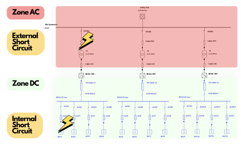
Unlike conventional power systems, fault currents in a BESS are largely shaped by the characteristics of the power conversion system electronics. This affects both the energy of an arc flash and how effectively that arc can be detected.
The operational consequences of short circuits include:
- accelerated cell degradation
- shutdown of the installation
- hazards during operation
The system-level consequences, for large installations, can include:
- disruption to grid stability
- cascading trips
- fire in the installation
Standards and Regulations — EU, USA, China
Awareness of electrical hazards is reflected in a whole range of legal regulations at both the European and national level:
- Directive 89/391/EEC of 12 June 1989, on measures to encourage improvements in the safety and health of workers at work. Article 6.2 sets out the general principles of hazard prevention.
- Regulation of the Minister of Energy of 8 June 2021, on occupational health and safety for energy equipment (Polish Journal of Laws, 2021, item 1210).
- EN 50110-1 — Operation of electrical installations, Part 1: General requirements.
A number of international standards have also been developed to address protection against arc-flash hazards:
- IEC 61482-2 — Live working: protective clothing against the thermal hazards of an electric arc, Part 2: Requirements
- IEC 61482-1-1 — Live working: protective clothing against the thermal hazards of an electric arc, Part 1-1: Test methods, Method 1 — Determining the arc parameters (ATPV, EBT50, ELIM) for flame-resistant clothing materials
- NFPA 70E — Handbook for Electrical Safety in the Workplace (2024 edition)
- IEEE 1584-2018 — IEEE Guide for Performing Arc-Flash Hazard Calculations
- ISSA Guide — Guideline for the selection of personal protective equipment when exposed to the thermal effects of an electric fault arc (2011)
- DGUV 203-077 — Thermal hazards due to electric fault arcing: guide for selecting personal protective equipment (2021)
When it comes to energy storage specifically, the following groups of standards are especially important and serve as a valuable knowledge base:
Europe / IEC:
- IEC 62933 (series) — Electrical Energy Storage (EES) systems (e.g. IEC 62933-1-1:2018 — Terminology; IEC 62933-5-2 — Safety requirements)
- IEC 62619:2022 — Secondary cells and batteries containing alkaline or other non-acid electrolytes: safety requirements for secondary lithium cells and batteries used in industrial applications
- IEC 62485 (series) — Safety requirements for secondary batteries and battery installations (e.g. IEC 62485-2:2018 — Stationary batteries)
USA:
- NFPA 855:2023 — Standard for the Installation of Stationary Energy Storage Systems
- UL 9540 — Energy Storage Systems and Equipment
- UL 9540A — Test Method for Evaluating Thermal Runaway Fire Propagation in Battery Energy Storage Systems
Chiny:
- GB/T 36276-2018 — Electrochemical Energy Storage System: Lithium-ion Battery Technical Specification
- GB/T 34131-2023 (updated version) — Technical Specification for Electrochemical Energy Storage Power Station
- NB/T 33015 (series) — Technical standards for electrochemical energy storage systems in power applications
- NB/T 33004 — Technical specification for grid-connected operation of electrochemical energy storage systems
| Area | Europe / IEC | USA | China |
|---|---|---|---|
| General BESS scope | IEC 62933 — Electrical Energy Storage Systems (EES) | UL 9540 — Energy Storage Systems and Equipment | GB/T 34131 — Technical Specification for Electrochemical Energy Storage Power Station |
| Battery safety (cells and modules) | IEC 62619 — Safety requirements for lithium batteries (industrial) | UL 1973 — Batteries for Use in Stationary Applications | GB/T 36276 — Lithium-ion Battery Technical Specification |
| System installation and integration | IEC 62485 — Battery installations | NFPA 855 — Installation of Energy Storage Systems | NB/T 33015 — Energy storage system technical requirements |
| Thermal runaway / fire testing | IEC 62933-5-2 — Safety requirements (system level) | UL 9540A — Thermal Runaway Fire Propagation Test | GB/T (partially covered within system-level testing) |
| Operational safety (OHS) | PN-EN 50110-1 — Operation of electrical installations | NFPA 70E — Electrical Safety in the Workplace | GB 26860 — Safety work regulations for electric power industry |
| Arc flash | IEC 61482 — Arc-flash protective clothing | IEEE 1584 — Arc-Flash Hazard Calculations + NFPA 70E | No dedicated standard — indirect approaches used |
To ensure an appropriate level of safety, law requires us to maintain a range of instructions and procedures — and these apply to energy storage installations too:
- Electrical Safety Plan (various countries use different names)
- Electrical Equipment Operation Instruction (equipment specific manuals)
- Distribution Network Operation and Maintenance Instruction (for distribution system operators)
- Workstation and general safety instructions
- Live-Working Procedure for electrical power equipment (where required)
Risk Management in BESS Operation
Effectively managing arc-flash risk calls for a systematic approach, made up of the following stages:
- assessing the arc-flash hazard
- assessing the electric-shock hazard
- assessing the condition of the equipment and installation
- making an initial selection of the required PPE
- assessing the risk and selecting the PPE required for the specific work being carried out
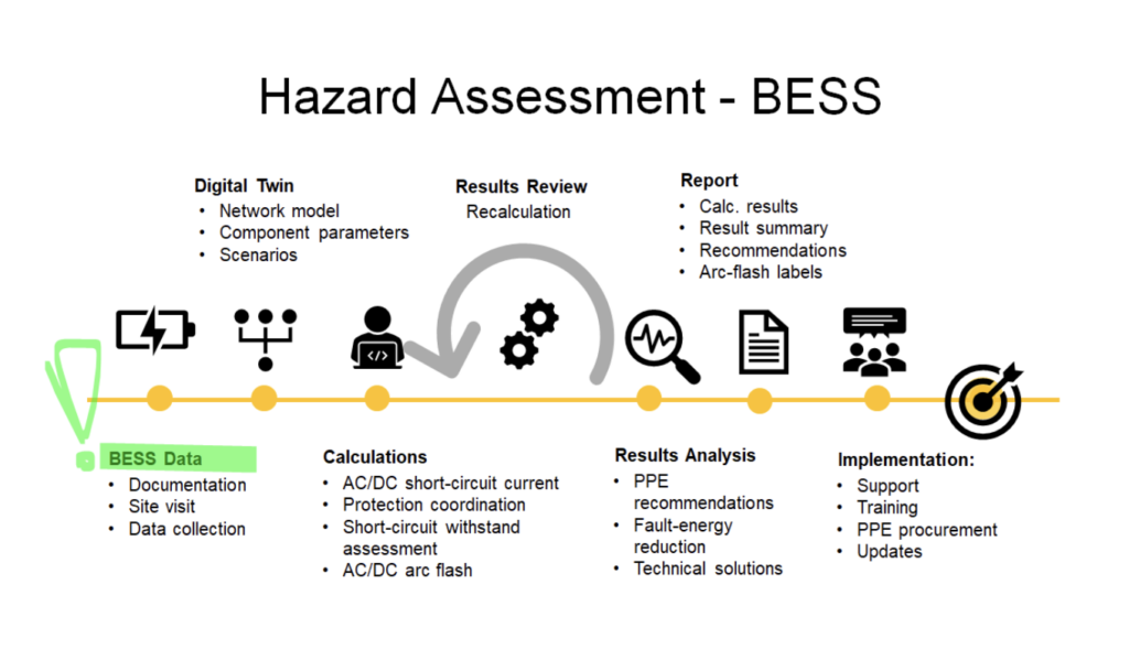
The first stage of the risk management process is identifying the potential locations where an arc-flash hazard could occur. Doing so lets us:
- determine the arc-flash energy level
- determine the arc flash boundary
- decide on further actions and recommendations
Once the hazard levels have been identified, the next step is to assess the shock risk — something that depends heavily on how the installationis built and on the work being performed. For example, by:
- determining the voltages involved
- determining which work is carried out near live parts
- determining which work is carried out on live parts
Then, by estimating how likely electrical hazards are for each individual task and operational activity, we can tailor our measures to:
- the level of the hazard
- the degree of exposure to it
- the condition and state of the equipment
- the work being carried out
This approach — developed by MR Power Systems as the “Simplified Task-Based PPE Risk Matrix” — makes it possible to control the protective measures used when working on electrical power equipment.
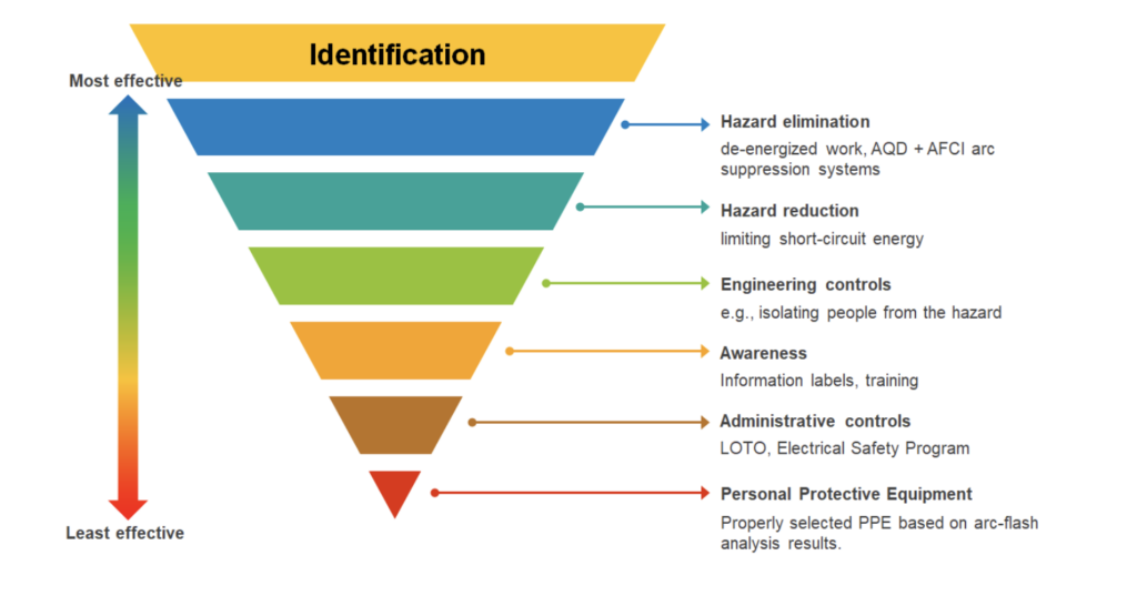
Effective risk management requires a systemic approach, and it begins with identifying and defining the hazards. From there, we naturally want to control and limit our exposure to whatever hazards are present. This is where the Hierarchy of Controls from NFPA 70E-2024 comes in, ordering the available actions from most effective to least:
- eliminate the hazard
- reduce the energy
- engineering controls
- awareness and training
- administrative controls
- personal protective equipment
Case Study: Victoria Big Battery
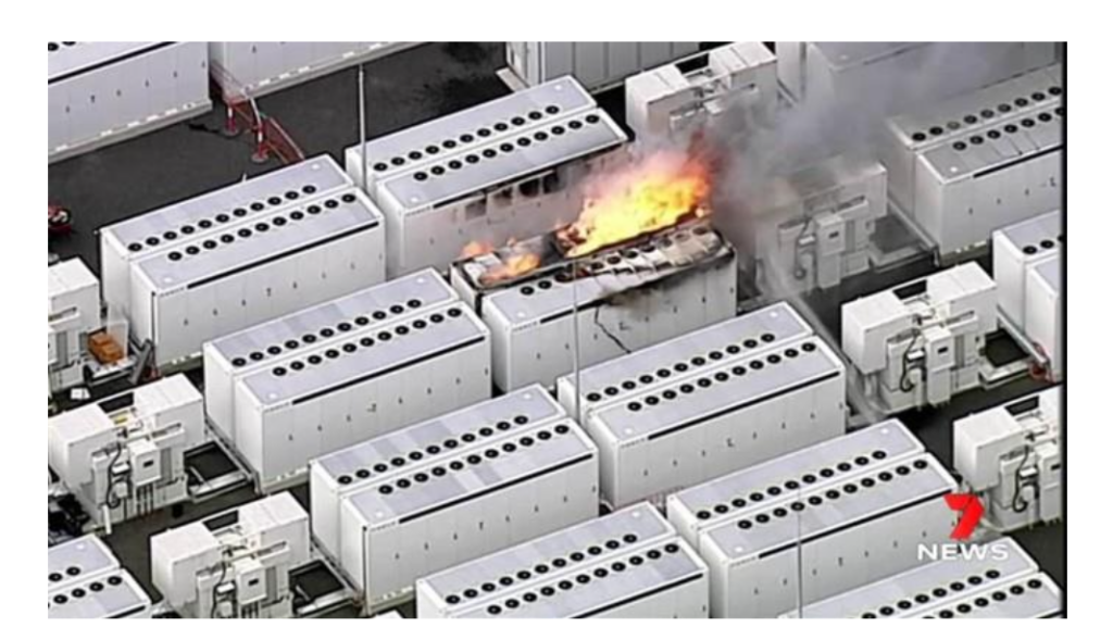
One of the best-known incidents involving energy storage was the fire at the Victoria Big Battery (300 MW / 450 MWh) in Australia in 2021. It happened during the system’s commissioning tests, and it stands as an important example of the risks specific to large-scale BESS.
The direct cause was an internal fault in one of the battery modules. A loss of coolant tightness was followed by a short circuit, which led to localized overheating and then triggered thermal runaway. With the thermal balance lost, the phenomenon spread to neighbouring modules within the container.
Despite the protective systems in place — detection systems and fire-suppression measures among them — the incident developed into a prolonged fire that burned for several days. Gas emissions and intense thermal effects were observed throughout, which forced a safety exclusion zone to be set up around the installation. Analysis of the event points to several key takeaways:
- an incident can be initiated at the level of a single module
- thermal runaway propagates within the container
- standard suppression systems may not be enough to stop the process, but they do help limit the scale of the fire and its spread
- early detection and module separation are critical
- BESS designs should account for escalation scenarios, not just single-point failures
The Tesla Big Battery case shows that hazards in energy storage are systemic in nature, and they demand an approach that covers both the design and the operation of the installation.
https://reneweconomy.com.au
Conclusion
Energy storage systems introduce a new level of complexity to electrical-power hazards — one that arises from the combination of DC short circuits, the difficulty of detecting arc faults, voltages above 1000 VDC, and the risk of an incident escalating to the point where a cell loses its thermal balance. Taken together, these factors mean the conventional approach to electrical safety is no longer sufficientEnsuring safe operation calls for an integrated approach that spans the design phase, the operation of the installation, and the analysis of hazards and risk. We should treat BESS containers like installations rather than products.
Would you like to know more?

Marcin Ruta
Electrical Safety Consultant
MR Power Systems