Arc Flash & Shock Hazard
Autor: Arkadiusz Fudela | MR Power Systems
Main topic : Arc flash and electric shock hazards in low-voltage switchgear: a real project case study covering exposed live parts, missing protective barriers, and practical measures to improve electrical safety.
Standards and designations mentioned: NFPA 70E, IEEE 1584, IP2X
Reading time : 10 min
Arc Flash Hazards
A real project example — what arc flash and shock hazard actually look like in an LV switchgear
There’s a lot of talk about arc flash and shock hazard in theory — incident energy calculations, PPE categories, NFPA 70E tables. But sometimes the best lesson is simply opening a panel door and seeing what’s inside.
That’s exactly what I want to show you today. The following example comes from one of our projects. The location stays anonymous — this isn’t about pointing fingers, it’s about awareness.
Step 01 — Identifying Hazards in LV Switchgear
What are we actually looking at?
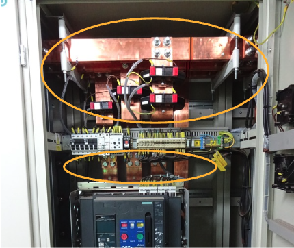
This is the main LV switchgear— the incomer fed directly from the transformer. One of the highest-energy points in the entire distribution system on site. Any accidental contact with live parts here carries serious — and often fatal — consequences.
At first glance, the installation might look functional. But a trained eye quickly picks up several critical issues, both from a shock protection and arc flash perspective.
Step 02 — Missing Barriers and Exposed Live Parts
Problem 1: No IP2X protection during normal operation
With the doors closed, IP2X is technically satisfied. But this switchgear cannot be operated with the doors closed — to see and operate the main breaker and every other breaker in the panel, you have to open them. In practice, this eliminates protection entirely during every operational task.
Problem 2: All live parts are fully exposed
Once the doors are open, everything energized is fully accessible. No insulating covers, no partial barriers, no separation between control wiring and the main busbars. The copper busbars are within arm’s reach — literally.
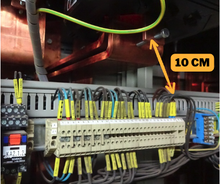
About those ~10 cm: a dropped wrench, a loose wire, an unintentional movement while working on cables — that’s all it takes to bridge that gap and initiate an arc. This is what arc flash hazard looks like in the real world — not a formula in a textbook, but a physical gap with the risk of releasing enormous energy.
Step 03 — Electric Shock Risk and Arc Flash Consequences
What does this mean in practice?
⚡ High electric shock risk. If a technician slips, trips, or momentarily loses their balance while working at this panel, they may instinctively grab the energized busbars or touch an energized busbar and another metal part at the same time. The outcome can be fatal.
💥 Incident energy estimated at >8 cal/cm². Based on the system configuration, the incident energy at this location is estimated to exceed 8 cal/cm² — though full calculations are still in progress. That puts this squarely at PPE Category 2 or above.
🧤 Full PPE required just to open the door. Because live parts are immediately exposed the moment the enclosure is opened, a full arc flash ensemble must be worn for every task — including simply opening the door to inspect the equipment, check protection status & settings. I spent two full working days on that site dressed that way.
🔲 Full PPE required to operate breakers. In a well-designed switchgear, routine breaker operation doesn’t require special PPE. Here, it does — every switching operation becomes a high-risk task. Better switchgear design would never create this situation in the first place.
Step 04 — How to Reduce Arc Flash and Electric Shock Risks
What needs to happen?
The good news: many of these issues are relatively inexpensive to fix. You don’t need to replace the entire switchboard — you need awareness, a plan, and the willingness to act.
A — Install insulating busbar covers
Dedicated busbar shrouds or custom-fabricated insulating barriers can restore effective IP2X protection even with the doors open. This is often a low-cost intervention with a significant safety impact.
B — Conduct a full arc flash study
Confirm incident energy levels through proper calculations per IEEE 1584. Establish correct arc flash boundaries and update equipment labels. Without this, PPE requirements are little more than educated guessing.
C — Ensure PPE availability and safe working procedures
Until the engineering fixes are in place, everyone working at this panel must have access to the right PPE, know what’s required, and follow a documented safe work procedure. This is not optional.
D — Document everything in a site visit report
All identified issues were captured in a formal site report. This creates accountability, enables tracking, and — critically — gives the client a clear record of what was found and what needs to change. Problems that are documented rarely quietly disappear without action.
Closing Thoughts
Arc flash and shock hazard aren’t abstract textbook risks. They exist in real facilities, in real equipment — right now. The installation shown here is not an exception — similar arrangements can be found in industrial plants across many countries, often without anyone stopping to ask the right questions.
The first step is always the same: identify the hazard. You cannot protect yourself from something you can’t see. That’s exactly why site visits and installation condition reviews matter — not to generate paperwork, but to create an opportunity to improve installation safety before someone gets hurt.
Have you come across similar setups in your country or facility?